Abstract
Taking mining area 2502 in the Huayan mine field which was affected by strong geological tectonic stress as an engineering background, the water jet technology is studied through in-site survey, laboratory test, theoretical analysis, numerical simulation, and field industrial test. The research results are as follows: the burst tendency of No. 5 coal seam can be reduced to a certain extent after softening with water, and then the water jet technology is used to prevent rock burst of roadways; the typical characteristics of rock-burst accidents mainly cause heaving floor and serious deformation of two sides. The occurrence mechanism of rock burst in roadway ribs has two different forms, and they are static load dominant type and dynamic load dominant type. The abutment stress concentration value is higher than a certain concentration static load, it will affect the coal and rock medium in the floor, and the coal and rock medium in the floor will be transformed into a plastic state and then occur rock burst; the water jet technology for roadway ribs can effectively prevent rock burst of roadway ribs and floor based on the dynamic and static loads superposition theory and Terzaghi theory. Based on the results of numerical simulation, the specific parameters of water jet technology for roadway ribs in 250204 tailgate are as follows: the diameter and length of initial borehole are 110 mm and 20.0 m, the diameter and length of water jet section are 500 mm and 15.0 m, and the spacing between adjacent water jet boreholes is 3.0 m; the monitoring result of signal intensity by EMR indicates that the decreasing amplitude of signal intensity of EMR is about 60.2% on the side of coal-pillar rib, and the decreasing amplitude of signal intensity of EMR is about 68.6% on the side of solid-coal rib; the convergences monitoring result indicates that the convergence ratio of roadway height is about 3.2%, and the convergence ratio of roadway width is about 2.3% in the pressure relief roadway part; the water jet technology is not only helpful to the prevention of rock burst for the roadway ribs but also can play a good prevention of rock burst for roadway floor. The research results provide a theoretical foundation and a new guidance for preventing rock burst in roadway ribs and floor with similar engineering geological conditions.
1. Introduction
During the underground mining and driving activities, the surrounding rock around mining or driving space is easy to cause rock burst under the superposition disturbance of high concentrated static load and strong dynamic load [1–4]. Therefore, it is necessary to take pressure relief and prevention measures for the coal and rock mass around the mining or driving space.
In recent years, due to the popularization of fully mechanized mining hydraulic support and the improvement of mining face support strength, most of the underground damage caused by rock burst occurs in the roadways. Statistics show that 75% of rock burst accidents occurs in two parallel roadways of the mining face. Therefore, the research on rock burst prevention of roadways under strong mine pressure condition is one of the main contents. There have been a lot of pressure relief measures for coal mass, such as pressure relief measures for large diameter drilling, pressure relief measures of coal seam water injection, and pressure relief measures for deep hole blasting [5, 6]. These conventional measures can relieve the pressure of coal and rock mass to a certain extent and then play a preventive effect of rock burst. In recent years, the water jet technology has also been applied to the coal mine rock burst prevention work. Because the burst tendency of coal and rock mass can be reduced in saturated water state (softening state), the water jet technology is used to relieve high pressure of surrounding rock and then prevent rock burst. The water jet technology has been used in underground mines for many years, and this technology has no spark, no dust, and no wear characteristics compared to traditional mechanical operation [7, 8].
Many scholars have studied the application of water jet technology in underground mining field. Shen et al. [9] analyzed the pressure relief mechanism of coal seam after special drill slots were formed in coal mass and showed that the special drill slots in coal mass could significantly improve permeability of coal seam and pressure relief degree and then effectively prevented coal and gas outburst. Shen [10] studied the coal mass breaking mechanism and indicated that the coal mass breaking includes three processes: crack generation, water wedge action, and surface scouring. The Fluent software is used to analyze the water jet force, water jet target distance, and punching radius, and the simulated results were applied to the prevention of gas outburst. Dou et al. [11, 12] studied the punching method of water jet technology in preventing rock burst and the specific construction parameters by Flac2D software, and the feasibility of this technology in preventing rock burst was verified by field industrial test. Yang et al. [13] studied the occurrence mechanism of rock burst in surrounding rock of roadways and indicated that using water jet to punch an initial borehole could form a water jet section (weak structure zone) inside the roadway ribs. This weak structure zone can transfer and release the high concentrated static load accumulated inside the roadway ribs and then prevent rock burst in roadway ribs.
It can be seen that many scholars have applied the water jet technology in the field of preventing rock burst; however, there is little research on whether this technology can satisfy the pressure relief effect in the area affected by strong geological structure. This paper takes mining area 2502 in the Huayan mine field which was affected by strong geological tectonic stress as an engineering background, and the application of water jet technology in roadway ribs is studied. The purpose is to verify the prevention of rock burst and pressure relief effect of water jet technology for roadway ribs and floor and then provide a theoretical foundation and a new guidance for preventing rock burst in roadway ribs and floor with similar engineering geological conditions.
2. General Situation of Geology
2.1. Mining and Engineering Geological Conditions
Huayan mine field, which is almost entirely located in the north of Huating County, Gansu Province, was affected by strong geological tectonic stress. Under the influence of this stress, the activities in this region have reached a climax, and the structural form of the fault fold belt on the western margin has been basically shaped after the Yanshan movement. As a result, the horizontal stress is much greater than the vertical stress in this mine field. A syncline axis and an anticline axis pass through the whole Huayan mine field under the influence of large folding structure. The main mining No. 5 coal seam is also affected by the large folding structure during its mining period. The geological structure plan of Huayan mine field is shown in Figure 1.

The Huayan mine field was officially divided into Huating, Yanbei, Shanzhai, and Chenjiagou coal mines for independent mining with the approval of the Ministry of land and resources in 2006. According to the geological exploration data of Huayan mine field, the relative position and mine field size of the whole Huayan mine field are shown in Figure 2. The main mining coal seam of Huating, Yanbei, Shanzhai, and Chenjiagou coal mines is the No. 5 coal seam, which is nearly horizontal. The strike angle of this coal seam is about 330°~345°, inclined to the west. The dip angle of this coal seam is about 0°~15°, and the mean thickness of this coal seam is 40.6 m. The No. 5 coal seam is an extra thick coal seam. The coal quality belongs to long flame coal with ultralow ash, ultralow sulfur, low-medium phosphorus, high volatile matter, medium and high calorific value, high chemical activity, and low melting point. It is easy to sort and excellent. All coal mines are equipped with domestic advanced fully mechanized top coal caving high-yield and high-efficiency equipment for layered fully mechanized top coal caving mining.

Among these coal mines in Huayan mine field, Yanbei coal mine is located in the middle of the Huayan mine field. It is adjacent to Shanzhai coal mine in the north, Huating coal mine in the south, Chenjiagou coal mine in the west, and local small coal mines in the east. At present, the main mining area in Yanbei coal mine is mining area 2502, which is about in the +860 m~+1171 m level elevation, and its corresponding ground level elevation is about in the +1557 m~+1580 m. The folding structure is developed in this mining area, with anticline axis in the east and syncline axis in the west. All the mining and driving faces are currently being mined or have been mined out cross a syncline structure, which lead to rock-burst accidents, and strong underground pressure appears continuously. There are no faults and other geological structures in this mining area. The thickness of No. 5 coal seam in mining area 2502 is 18.2 m~54.5 m, with a mean thickness of 31.0 m. The layered fully mechanized top coal caving mining technology is adopted in panels of mining area 2502. At present, the first layer (upper layer) is being mined, with a thickness of 9.5 m~15.4 m and a mean thickness of 12.0 m. The mining height of panels in mining area 2502 is 3.0 m, with a top coal caving height of 9.0 m, and the ratio between mining and caving is about 1 : 3. The first panel in the mining area 2502 is the panel 250205, and it has been mined out currently. The panel 250206 that can be seen as a succeeding panel of the panel 250205 is now being mined, and it is the second panel in the mining area 2502. The panel 250204 that can be seen as a succeeding of the panel 250206 is now being driven, and it is the third panel in the mining area 2502. The plan of mining and driving engineering in the mining area 2502 is shown in Figure 3.

2.2. Burst Tendency Test Result of No. 5 Coal Seam
2.2.1. The Burst Tendency Test Indexes
According to China’s national standard (GB/T 25217.2-2010) of coal burst tendency classification and index determination method [14, 15], coal samples that are taken from the No. 5 coal seam in the mining area 2502 and then the standard specimens (the specific size of each cylinder:) were processed, and the mechanical properties are tested in a laboratory with corresponding qualifications. The coal-burst tendency judgment standard is shown in Table 1.
INLINE FX
According to Table 1, when the burst tendency test indexes of , , , and are contradictory, the number of test standard specimens should be increased, and their classification can be carried out by fuzzy comprehensive evaluation method or probability statistics method.
2.2.2. The Test Methods
The coal burst tendency in natural state and saturated water state (softening state) should be measured, respectively, that is, one loading test and cyclic loading test should be conducted for 6 times, respectively, so a total of 12 coal standard specimens need to be processed. 14 coal standard specimens are processed in this test, two of which are for standby. The coal samples are taken from different locations in the mining area 2502, and then, they are processed into coal standard specimens with cylindrical size of (). The picture of coal samples before and after processing is shown in Figure 4.

(a)

(b)
In this test, the coal burst tendency in natural state and saturated water state (softening state) needs to be measured, respectively. Therefore, 7 coal standard specimens are completely immersed in clean water for more than 48 hours in advance (fully ensure that coal standard specimens are saturated with water), and the other 7 coal standard specimens are wrapped in sealed bags and stored in dry state. The experimental loading device adopts SANS material testing machine produced by Shenzhen xinsansi material testing Co., Ltd., which is high-precision and can control the loading speed, and is used to measure the coal standard specimen loading and the whole process curve of stress strain. This experimental machine can set the loading mode manually, and the loading process is directly controlled by the computer. The experimental machine (SANS material testing machine) is shown in Figure 5.

In order to get burst tendency test indexes of , , , and , the corresponding test methods are as follows [16]: (a)Dynamic failure time (): measuring the load borne by the coal standard specimens with the load sensor until these specimens are damaged. The measured signals are transmitted to the computer data acquisition and processing system through the dynamic resistance strain gauge. According to the measured data, the system directly draws the corresponding dynamic failure time curve, enlarges the key part of the maximum failure load in this curve, and accurately gives the dynamic failure time () value(b)Elastic energy index (): the cyclic loading method is adopted to load the coal standard specimens to about 75%~85% of the load limit, then unload to a small load, and then continue to load until these specimens are completely damaged. The load borne by these specimens is measured by the load sensor, and the axial deformation of these specimens is measured by the displacement sensor. The measured signals are recorded and stored by the computer data acquisition system, and after data processing, the calculation diagram of elastic energy index is drawn to calculate the elastic energy index () value(c)Burst energy index (): under uniaxial compression, the coal standard specimens are directly loaded at one time until they are completely destroyed. The load borne by these specimens is measured by the load sensor, and the axial deformation of these specimens is measured by the displacement sensor. The measured signals are recorded and stored by the computer data acquisition system, and the calculation diagram of burst energy index is drawn after data processing to calculate the burst energy index () value(d)Uniaxial compressive strength (): the uniaxial compressive strength of coal standard specimens is directly recorded by the signal recorder during the loading process of the press, and the uniaxial compressive strength () value is calculated according to the maximum pressure and the parameters of the corresponding coal standard specimen
2.2.3. The Test Results
The dynamic failure time () parameters of coal standard specimens in natural state and saturated water state (softening state) obtained by the test are shown in Table 2.
The elastic energy index () parameters of coal standard specimens in natural state and saturated water state (softening state) obtained by the test are shown in Table 3.
The burst energy index () parameters of coal standard specimens in natural state and saturated water state (softening state) obtained by the test are shown in Table 4.
The uniaxial compressive strength () parameters of coal standard specimens in natural state and saturated water state (softening state) obtained by the test are shown in Table 5.
Combined with Tables 2, 3, 4, and 5, the burst tendency test result of the No. 5 coal seam is determined, as shown in Table 6.
It can be seen from Table 6 that the No. 5 coal seam has a strong burst tendency in natural state, and it has a weak burst tendency in saturated water state (softening state). This shows that the burst tendency of the No. 5 coal seam can be reduced to a certain extent after softening with water.
2.3. Typical Characteristics of Rock-Burst Accidents
According to the monitoring records of rock-burst accidents of panels 250205 and 250206 in the mining area 2502 during their mining periods, the typical characteristics of mine pressure behaviors can be counted as shown in Table 7.
According to Table 7, it can be seen from these monitoring records of panels 250205 and 250206 (1#~7# monitoring records belong to the panel 250205 and 8#~16# monitoring records belong to the panel 250206) that almost all of the typical rock-burst accidents occurred during their mining periods were located in syncline geological structure influence area. These typical mine pressure behaviors mainly caused heaving floor and serious deformation of two sides. The typical surrounding rock failure forms of roadways on site are shown in Figure 6.

(a)

(b)

(c)
According to Figure 6, it can be seen that the typical mine pressure behavior of ribs is extrusion deformation, which means that there are high stresses concentrated in both ribs of the roadway. The high stress concentration is caused by the superposition of mining stress and self-weight stress caused by buried depth. It also can be seen that the typical mine pressure behavior of floors is heaving floor, and the deformation degree of heaving floor is different, severe in some places, mild in others. When the deformation degree of heaving floor is serious, the section shrinkage of roadway is large, and the roadway cannot meet normal production operation, and even cause equipment damage and casualties. Therefore, it is necessary to take effective methods to relieve the pressure of roadway surrounding rock. In particular, pressure relief is carried out for floor and two ribs of roadway.
3. Occurrence and Prevention Mechanisms of Rock Burst
3.1. Occurrence Mechanism of Rock Burst in Roadways
3.1.1. The Occurrence Mechanism in Roadway Ribs
Based on the superposition mechanism of dynamic and static loads, the occurrence mechanism of rock burst in roadway ribs has two different forms, and they are static load dominant type and dynamic load dominant type, respectively [17, 18]. The occurrence mechanism schematic diagram of rock burst in roadway ribs is shown in Figure 7.

(a)

(b)
According to Figure 7(a), it can be seen that the static load dominant type of rock burst is caused by high concentration static load (), and the concentration static load is enough to induce rock burst. Then, a rock-burst accident is induced by instantaneous instability and failure of a certain range of coal mass in shallow part of the roadway ribs; according to Figure 7(b), it can be seen that the dynamic load dominant type of rock burst is caused by strong dynamic load disturbance (), and the concentration static load is not enough to induce rock burst. Then, a rock-burst accident is induced by instantaneous instability and failure of a certain range of coal mass in shallow part of the roadway ribs. No matter what kind of rock burst, the occurrence positions are all a certain range of coal mass in shallow part of the roadway ribs. Therefore, it is necessary to take targeted measures to relieve pressure and prevent rock burst.
3.1.2. The Occurrence Mechanism in Roadway Floor
When a roadway is located in syncline geological structure influence area, the horizontal tectonic stress () is at a high level, and a certain range of coal mass in shallow part of the roadway floor is in a state of plastic deformation due to extrusion of higher horizontal tectonic stress. Based on the Thessarky theory [19], it can be known that when the vertical stress caused by a certain range of coal mass in shallow part of the roadway ribs exceeds a certain value instantly, it will cause a certain range of coal mass in shallow part of the roadway floor to be unstable and destroyed instantly and then induce a rock-burst accident. The occurrence mechanism schematic diagram of rock burst in roadway floor is shown in Figure 8.

3.2. Prevention Mechanism of Rock Burst in Roadways
3.2.1. The Prevention Mechanism in Roadway Ribs
According to the above analysis of coal standard specimens in natural state and saturated water state (softening state), it can be concluded that the water can effectively soften a certain range of coal mass in shallow part of the roadway ribs, and then the burst tendency test indexes of coal seam are reduced. Under the circumstances, the certain range of coal mass in shallow part of the roadway ribs is not easy instantaneous instability and failure, and then a rock-burst accident is not easy to occur in roadway ribs. Therefore, the water jet technology is used to prevent rock burst of roadway ribs. The prevention mechanism schematic diagram of rock burst in roadway ribs is shown in Figure 9.

According to Figure 9, the prevention mechanism of rock burst by water jet technology can be obtained by comparing this pressure relief measure before and after using on the roadway ribs. From the perspective of elastic strain energy, before using the pressure relief measure of water jet technology, when the elastic strain energy () accumulated in rock burst start-up zone (I) is greater than the critical value of induced rock burst, a certain range of coal mass in rock burst start-up zone (I) is unstable and destroyed instantly, then the rock burst start-up zone (I) becomes activated. However, after using the pressure relief measure of water jet technology, when the elastic strain energy () accumulated in rock burst start-up zone (II) is greater than the critical value of induced rock burst, a certain range of coal mass in rock burst start-up zone (II) is unstable and destroyed instantly, then the rock burst start-up zone (II) becomes activated. But the rock burst start-up zone (II) is in the depth part of the roadway rib and there is a water jet zone (weak structure zone) in the path of its energy propagation and release. The water jet zone (weak structure zone) can effectively absorb and scatter the elastic strain energy () in its propagation process, and the residual elastic strain energy () accumulated in rock burst start-up zone (III) is at a low level. At the moment, the rock burst start-up zone (III) is not easy to activate and the roadway rib is not prone to rock burst occurrence.
From the perspective of abutment stress, it can be seen that the existence of water jet zone (weak structure zone) makes the initial “single peak” curve change to a final “double peak” curve, and the initial single peak high concentration static load () changes to a final double peak concentration static loads ( and ), and these concentration static loads satisfy the following conditions: . The distance relation between these concentration static loads and the roadway rib satisfies the following conditions: . It can be seen that after taking water jet technology, the high concentration static load () is transferred to the depth part of the roadway rib, and the stress concentration degree is reduced as peak concentration static load (). This means that static load dominant type of rock burst will not occur.
In addition, after using the pressure relief measure of water jet technology, there will be a lot of water left in the water jet zone (weak structure zone), and it will play an auxiliary role in softening the coal mass in shallow part of the roadway rib. This will further reduce the possibility of the occurrence of rock burst in roadway rib.
3.2.2. The Prevention Mechanism in Roadway Floor
It is assumed that when the abutment stress concentration value is higher than concentration static load (), it will affect the coal and rock medium in the floor, and the coal and rock medium in the floor will be transformed into a plastic state. Based on the Terzaghi theory, the prevention mechanism schematic diagram of rock burst in roadway floor is shown in Figure 10.

According to Figure 10, from the perspective of abutment stress, before using the pressure relief measure of water jet technology, the width range of abutment stress concentration value higher than concentration static load () can be defined as ; after using the pressure relief measure of water jet technology, there is a certain range of pressure relief zone that does not meet the abutment stress concentration value higher than concentration static load (), so the width range of abutment stress concentration value higher than concentration static load () is discontinuous and it can be defined as and . According to the research results of relevant literature, the width ranges of abutment stress concentration value higher than concentration static load () satisfy the following conditions: . Therefore, the superposition area of plastic state zones ( and ) is less than the area of plastic state zones (). After using the pressure relief measure of water jet technology, the area of plastic zone in floor is smaller and its degree of heaving floor caused by instantaneous sliding instability will be reduced. It can be seen that after the pressure relief measure of water jet technology is taken for the roadway ribs, the prevention effect of rock burst in floor can be achieved at the same time.
4. Mechanism Analysis of Water Jet Technology
4.1. Introduction of Water Jet Technology
The construction process of water jet technology for roadway rib is as follows: (a)Firstly, it is necessary to drill an initial borehole on the roadway rib with an ordinary drill bit, and the borehole diameter () should meet the requirements of subsequent water jet punching. If this is not done, the nozzles can easily be blocked by pulverized coal during subsequent operations. Therefore, based on the selected model of water jet drill bit (model ZJN94/3), the initial borehole diameter should be greater than 94 mm, and then an ordinary drill bit with diameter of 110 mm is adopted(b)Secondly, when the length of an initial borehole () reaches its design length, the ordinary drill bit is backlogged and replaced with a water drill bit (model ZJN94/3). The water drill bit (model ZJN94/3 cannot be used directly for drilling to prevent the nozzles from being blocked by pulverized coal. Then, according to the initial design, the water jet drill bit is used to punch the initial borehole, and then a length of punching section () is formed, namely, water jet section. In order to prevent safety accidents caused by borehole return water with slag, the residual length of this initial borehole () can be seen as a protected zone without punching by water jet drill bit. The diameter of water jet section () is determined by the water jet parameters(c)Thirdly, the water supply is provided by pumping, and the water pressure is regulated by BOTK-01 series water pressure regulating systems. The drill stems are hollow, and they are connected in turn to provide water supply path. When the adjusted water supply reaches the position of water jet drill bit through this path, finally water supply is sprayed out by three nozzles on the water jet drill bit, and the three nozzles are 120° to each other(d)Finally, the three water jets punch the initial borehole wall by rapidly rotating with the water jet drill bit and continuously moving axially with the drill stems (hollow), and then, a water jet section is formed. This water jet section can play a good pressure relief effect for the roadway ribs and floor
The schematic diagram of water jet technology for roadway rib is shown in Figure 11.

4.2. Punching Mechanism of Water Jets
When the water supply is sprayed out of the nozzles, it will change into water jets and punch the initial borehole wall. The number of water jets is determined by the number of nozzles on the water jet drill bit. Based on the water drill bit (model ZJN94/3), it can be known that there are three water jets punching the initial borehole wall. The punch capacity of water jets can be adjusted by changing nozzles with different diameters (). The schematic diagram of water jets punching initial borehole wall is shown in Figure 12.

(a)

(b)
When the pressure and quantity of flow parameters of water supply are determined, the theoretical quantity of flow of these nozzles is also determined accordingly. The theoretical quantity of flow can be calculated by the following formula [20]: where is the theoretical quantity of flow of these nozzles; is the equivalent diameter of these nozzles; and is the pressure of water jet at the nozzle exit.
The practical quantity of flow of these nozzles is depended by the geometric shape, inner surface roughness, and internal flow state of these nozzles, which is mainly determined by the field test. According to the statistical results of relevant literatures [21], the flow coefficients under different models of nozzles are shown in Table 8.
Therefore, the practical quantity of flow of these nozzles can be calculated by the following formula: where is the practical quantity of flow of these nozzles, calculated in terms of flow per minute; is the flow coefficient.
For multiple nozzles, they should be converted into equivalent diameter of nozzles for calculation. The equivalent diameter can be expressed as the following formula: where is the equivalent diameter of nozzles; is the number of nozzles.
Since the practical quantity of water flow is better monitored in practice and the model of nozzles can also be determined in advance, according to Equations (1) and (2), its expression can be known as the following formula:
During the water jets punching, the dynamic pressure of water jets acting on the initial borehole wall causes the internal stress in the coal mass of initial borehole wall. When the maximum shear stress of this internal stress exceeds the ultimate compressive strength of the coal mass, the coal mass is damaged. Therefore, in order to destroy the coal mass of initial borehole wall and form a larger range of water jet section, it is necessary to make the pressure of water jet at the nozzle exit greater than the ultimate compressive strength of the coal mass.
According to Figure 11, the nozzle model can be seen as an extension stub and its flow coefficient (μ) is about 0.82. The diameter of this nozzle model for water jet drill bit (model ZJN94/3) is 1.6 mm, 2.0 mm, 2.5 mm, and 3.0 mm, respectively. Assuming that the adjustable range of practical quantity of flow for water supply is about 100 L/min~300 L/min, and then based on Equation (4), the change law of pressure of water jet at the nozzle exit can be obtained as shown in Figure 13.

According to Figure 13, it can be seen that the pressure of water jet at the nozzle exit increases exponentially with the increasing of practical quantity of flow for water supply under any nozzle diameter condition. Under the same practical quantity of flow for water supply condition, the smaller the nozzle diameter is, the greater the pressure of water jet at the nozzle exit is. According to Table 5, the mean uniaxial compressive strength of coal standard specimens from No. 5 coal seam in mining area 2502 has been known to be 15.4 MPa. Then, combining with Figure 13, it can be seen that when the diameter of this nozzle model for water jet drill bit (model ZJN94/3) is 1.6 mm, 2.0 mm, and 2.5 mm, there is a pressure of water jet at the nozzle exit that can provide higher strength than the mean uniaxial compressive strength of the No. 5 coal seam under certain practical quantity of flow for water supply. But when the diameter of this nozzle model for water jet drill bit (model ZJN94/3) is 3.0 mm, the practical quantity of flow for water supply is almost 300 L/min, and the corresponding pressure of water jet at the nozzle exit can be higher than 15.4 MPa. Therefore, this nozzle model with diameter of 3.0 mm is not considered. The larger the practical quantity of flow for water supply is, the stronger the slag carrying capacity of return water is. Therefore, this nozzle model with diameter of 2.0 mm is selected for field industrial test, and the practical quantity of flow for water supply should be higher than 236 L/min and less than 300 L/min.
5. Field Industrial Test
5.1. The Implementation Method
5.1.1. The Determination of Spacing and Diameter Parameters
The panel 250204 is now being driven, and it is the third panel in the mining area 2502. The field industrial test is carried out on the ribs of 250204 tailgate before its mining stage. The water jet pressure relief measure is applied to roadway part in syncline geological structure influence area. The mean buried depth of the panel 250204 is about 580 m. It is assumed that the corresponding diameters of water jet section () are taken as 200 mm, 300 mm, and 400 mm, respectively. Then, the spacing between adjacent water jet boreholes () can be determined by numerical simulation method, and the numerical simulation results of different spacing between adjacent water jet boreholes are shown in Figure 14.

(a)

(b)
It can be seen from Figure 14(a) that the vertical stress between adjacent water jet boreholes begins to overlap slightly on the condition of diameter 300 mm and further at the diameter of 400 mm. As the diameter of these adjacent water jet boreholes is further increased, the vertical stress between adjacent water jet boreholes begins to overlap adequately and the coal mass between adjacent water jet boreholes changes into plastic state at the diameter of 500 mm. The plastic state zone between each two adjacent water jet boreholes is connected to form a wide range of pressure relief structure zone, and this zone can effectively transfer and release the high concentrated static load in roadway rib.
It can be seen from Figure 14(b) that when the spacing between adjacent water jet boreholes () increases from 3.0 m to 5.0 m, the vertical stress between adjacent water jet boreholes cannot overlap adequately at diameters of 300 mm, 400 mm, and 500 mm. At this point, if the vertical stress between adjacent water jet boreholes can overlap sufficiently, it is necessary to further increase the diameter of these adjacent water jet boreholes. Considering that too large diameter of water jet boreholes requires more pressure of water jet at the nozzle exit and time for punching, and the stability of water jet boreholes is poor, it is not suitable to set too large spacing between adjacent water jet boreholes.
In summary, the relatively reasonable spacing between adjacent water jet boreholes is determined to be 3.0 m and the corresponding diameter of water jet section is determined to be 500 mm.
5.1.2. The Determination of Length Parameter
The water jet borehole length () can be determined by numerical simulation results. Before pressure relief by using water jet technology for the roadway rib, the change law of abutment stress curve is shown in Figure 15(b). It can be seen that the abutment stress curve can be divided into three zones, and they are the reduced pressure zone (I), the increased pressure zone (II), and the stable pressure zone (III) from the outer roadway rib to the inner coal mass, respectively. High concentrated static load is easy to accumulate in the increased pressure zone (II) and then induces the coal mass instant instability and the occurrence of rock burst under the condition of static and dynamic loads superposition. Therefore, the water jets should be mainly used to punch the increased pressure zone (II) and the water jet borehole length () can be determined by numerical simulation method. According to the numerical simulation results in Figure 15(b), the width of increased pressure zone (II) is about 15.0 m, and then the corresponding water jet borehole length () can be taken as 15.0 m. The residual length of this initial borehole () can be determined to be 5.0 m.

(a)

(b)
With the increase of abutment stress in the coal mass, the microcracks in the coal mass will be further compacted, and the permeability of the coal mass will be further reduced. A steady flow method is also used to verify the position of stress peak, and its schematic diagram is shown in Figure 15(a). This method mainly forms a certain confined space in an initial borehole through two sealed capsules with certain water pressure (usually for 2.0~3.0 MPa), and the certain water pressure can be adjusted by pressure gage. The dimension of connecting rod between two sealed capsules is 1.0 m. When the certain confined space is formed in an initial borehole, use nitrogen gas cylinder to supply gas to this confined space and keep the flow stable by a flowmeter. According to this method, the position where the flow stability is minimum, that is, the position of peak stress, can be measured. As shown in Figure 15(b), the minimum steady flow position is about 10 m away from the roadway rib, which basically overlapped with the numerical simulation peak stress position, further verifying the accuracy of the simulation results.
After pressure relief by using water jet technology for the roadway rib, the change law of abutment stress curve is also shown in Figure 15(b). It can be seen that the stress in the increased pressure zone (II) has been transferred and released, and almost all the stress in this zone is less than 14.5 MPa at this time. It can be seen that water jets punching can play a good pressure relief effect in the coal mass of increased pressure zone (II), so as to effectively prevent the occurrence of rock burst.
5.1.3. The Specific Construction Scheme
According to the specific parameters of water jet boreholes determined above, the field engineering application is carried out on the two ribs of the 250204 tailgate, namely, the coal-pillar rib and the solid-coal rib. The length of the 250204 tailgate for field engineering application is about 60 m. Before using water jet technology, the initial boreholes with a diameter of 110 mm are adopted on both coal-pillar rib and solid-coal rib, and 21 initial boreholes with an interval of 3.0 m are constructed symmetrically on the coal-pillar rib and solid-coal rib. The orifice position of every initial borehole is about 1.2 m~1.5 m away from the floor, and the inclination of every initial borehole is about 3°~5°, which is conducive to the return water and slag carrying in the subsequent water jet construction; after using water jet technology, when the length of an initial borehole reaches 20.0 m, the ordinary drill bit is backlogged and replaced with a water drill bit (model ZJN94/3). Then, according to the above analysis, the water jet drill bit is used to punch the initial boreholes, and then water jet sections with a length of 15.0 m and a diameter of 500 mm is formed inside the roadway ribs. The specific construction scheme of water jet technology in the 250204 tailgate is shown in Figure 16.

5.2. The Field Monitoring Results
5.2.1. The EMR Monitoring Result
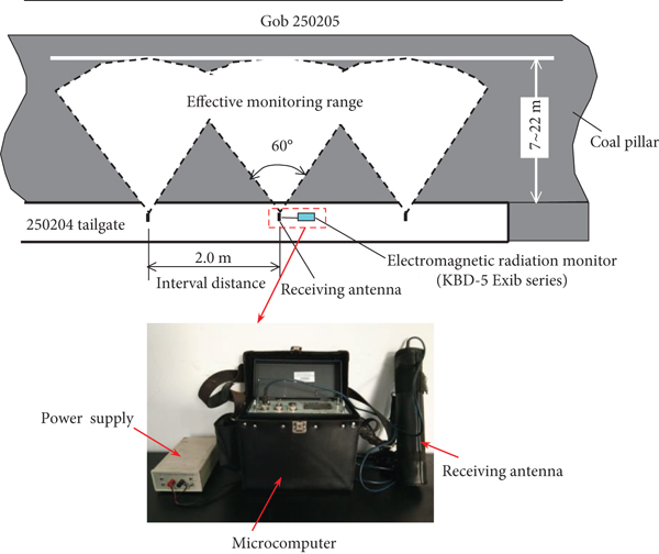
As the signal intensity of electromagnetic radiation (EMR) is positively correlated with the stress state of coal mass inside roadway ribs [22]; therefore, a KBD-5 Exib series of electromagnetic radiation monitor is used to monitor the change law of stress state for coal mass inside the roadway ribs. Before and after using water jet technology on the roadway ribs, a receiving antenna is used to monitor the roadway ribs by noncontact means, and the interval distance of adjacent monitoring points is about 2.0 m. The effective monitoring of maximum depth for this EMR is 22 m, and it can meet the requirements of field monitoring. The monitoring diagram of coal-pillar side is shown in Figure 17.
According to Figure 17, the monitoring result of signal intensity by EMR on solid-coal rib and coal-pillar rib is shown in Figure 18. It can be seen from Figure 18 that the overall signal intensity of EMR after using water jet technology is lower than that before using water jet technology. On the side of coal-pillar rib, the mean signal intensity of EMR before using water jet technology is about 44.2 mV, and the mean signal intensity of EMR after using water jet technology is about 17.6 mV. The decreasing amplitude of signal intensity of EMR is about 60.2%, as shown in Figure 18(a); on the side of solid-coal rib, the mean signal intensity of EMR before using water jet technology is about 49.7 mV, and the mean signal intensity of EMR after using water jet technology is about 15.6 mV. The decreasing amplitude of signal intensity of EMR is about 68.6%, as shown in Figure 18(b).

(a)

(b)
The above analysis shows that the water jet technology for roadway ribs can well relieve and transfer the high concentration stress accumulated in coal mass inside the roadway ribs and then makes the coal mass inside the roadway ribs in a good stress environment.
5.2.2. The Convergences Monitoring Result
After using water jet technology, a “cross-shaped” observation method is used to monitor the convergences of surrounding rock in the pressure relief roadway part [23]. The convergences of surrounding rock are monitored mainly through the pegs installed on the roadway surface, and the corresponding measurement tools are lines, telescoping rods, and trpes. The pegs can be divided into roof peg, rib pegs, and floor peg, and their arrangement is shown in Figure 19(a). According to Figure 19(a), it can be seen that the roof peg and floor peg are installed in the middle of the roof and floor, respectively, and the rib pegs are symmetrically installed 2.0 m away from the floor. A total of 3 groups of measuring stations are arranged in the pressure relief roadway part with an interval distance of 15 m, and the mean convergences monitoring result are shown in Figure 19(b).

(a)

(b)
According to Figure 19(b), it can be seen that the mean convergence of roof to floor increases with the increase of observation time, and the maximum mean convergence of roof to floor is about 129 mm at 38 days; the mean convergence of solid-coal rib to coal-pillar rib also increases with the increase of observation time, and the maximum mean convergence of solid-coal rib to coal-pillar rib is about 109 mm at 38 days. The mean convergence rates of roof-to-floor and solid-coal rib to coal-pillar rib both begin to decrease at 20 days and then stabilize at 29 days.
As the width and height of 250204 tailgate are 4.8 m and 4.0 m, respectively, the convergence ratio of roadway height is about 3.2% and the convergence ratio of roadway width is about 2.3%. Both the convergence ratios of roadway height and width are controlled within 5.0%, which means that the control effect of surrounding rock for the 250204 tailgate is good. It can be seen that the effective pressure relief for the ribs is also helpful for the pressure relief of the floor and thus improve the stress environment of coal and rock medium in the floor. Therefore, the water jet technology is not only helpful to the prevention of rock burst for the roadway ribs but also can play a good prevention of rock burst for roadway floor.
6. Conclusions
(1)Huayan mine field was affected by strong geological tectonic stress, and the horizontal stress is much greater than the vertical stress in this mine field. The mining and driving spaces are easily affected by this strong geological tectonic stress and then induce rock burst. Based on the burst tendency test result of No. 5 coal seam before and after saturated water state, the burst tendency of No. 5 coal seam can be reduced to a certain extent after softening with water(2)According to the monitoring records of rock-burst accidents of panels 250205 and 250206 in the mining area 2502 during their mining periods, these typical mine pressure behaviors mainly caused heaving floor and serious deformation of two sides. Therefore, it is necessary to take effective methods to relieve the pressure of floor and two ribs of roadway(3)Based on the superposition mechanism of dynamic and static loads, the occurrence mechanism of rock burst in roadway ribs has two different forms, and they are static load dominant type and dynamic load dominant type, respectively. No matter what kind of rock burst, the occurrence positions are all a certain range of coal mass in shallow part of the roadway ribs. Therefore, it is necessary to take targeted measures to relieve pressure and prevent rock burst. Based on the Thessarky theory, it can be known that when the vertical stress caused by a certain range of coal mass in shallow part of the roadway ribs exceeds a certain value instantly, it will cause a certain range of coal mass in shallow part of the roadway floor to be unstable and destroyed instantly and then induce rock burst(4)The water can effectively soften a certain range of coal mass in shallow part of the roadway ribs, and then, the burst tendency test indexes of coal seam are reduced. Therefore, the water jet technology is used to prevent rock burst of roadway ribs. After the pressure relief measure of water jet technology are taken for the roadway ribs, the prevention effect of rock burst in floor can be achieved at the same time(5)The field industrial test is carried out on the ribs of the 250204 tailgate before its mining stage. The EMR monitoring result shows that the water jet technology for roadway ribs can well relieve and transfer the high concentration stress accumulated in coal mass inside the roadway ribs and then make the coal mass inside the roadway ribs in a good stress environment; the convergences monitoring result shows that the effective pressure relief for the ribs is also helpful for the pressure relief of the floor and thus improve the stress environment of coal and rock medium in the floor
Data Availability
All data used to support the findings of this study are included within the article, and there are no any restrictions on data access.
Conflicts of Interest
The authors declare no conflicts of interest.
Acknowledgments
The work is supported by the Key Project of National Natural Science Foundation of China (Nos. 51634001, 51574243, 51404269, and 51674253).