Abstract
Universal tapered segmental ring system has been adopted to assemble tangent and curve line elements into the shield tunnels through the relative rotation of the adjacent front and rear rings, which simplifies the formwork design, demonstrates strong universality, and is easy for quality assurance. To evaluate the position deviation caused by the taper value and propose the assembly scheme for the contractor, this article developed the universal tapered segmental ring assembly simulation technology. Firstly, the assembly procedure of the universal tapered segmental ring system both in normal case and in special case is introduced, including the interval tunnel of special rings and actual engineering that needs deviation correction. Secondly, relevant core algorithms are introduced in detail, including the coordinate position algorithm of horizontal and vertical curves and computer graphic algorithm of spatial point rotating around any axis. Finally, this article takes a background metro line tunnel as a case to validate the algorithm and illustrate the assessment methodology of universal tapered segmental ring assembly accuracy. The sections with maximum deviation are found as an alert ahead of the shield advancing. In conclusion, the algorithms and methodology proposed in this article illustrate the excellent suitability and robustness in shield tunnels adopting a universal tapered segmental ring system in the stage of both design and construction.
1. Introduction
The shield-driven tunneling method is widely adopted and applied in the construction of urban underground tunnels in soft ground due to its flexibility, cost-effectiveness, and small impact on the ground surface [1]. TBM also has wide application in most urban subway tunnels in China.
There are two main forms of shield tunnel lining segmental ring systems, which are the traditional segmental ring (TSR) system and the universal tapered segmental ring (UTSR) system. A tunnel adopting the TSR system usually consists of a number of standard rings, as well as left and right turning rings featuring a tapered shape. Standard rings are used in tangent line sections, whereas turning rings are used in curved sections. ITA Working Group No. 2 [2] introduced an equation to calculate the taper value, which is defined as the difference between the maximum width and the minimum width. In that equation, the factor of vertical alignment is ignored. To fit the vertical curve, rubber cushion blocks of different thickness are usually used.
UTSR system, which features the circumferential surface of the ring inclined to the tunnel axis on one side or both sides (Figure 1), has already become a trendy assembly method around the world, for example, Shangzhong Road Tunnel in Shanghai, China, Yangtze River Tunnel in Shanghai, China, and Qianjiang Tunnel in Zhejiang, China, as well as increasing metro line tunnels. In this case, both horizontal and vertical alignment can be approximated through rotating the preceding and following rings. Therefore, only one type of universal tapered segmental ring is demanded for the whole length of an interval tunnel and only one set of formworks is required in precast plants. As a result, it is conducive to guarantee the precasting quality. In theory, the ring taper value can be decided according to three elements, including the outer diameter of the segment ring, average ring length, and the minimum curve radius [3]. To guarantee the precision of the actual tunnel, an axial UTSR system should address three problems as follows:(1)Small curve radius: due to the highly restricted construction circumstances in downtown areas with high density of buildings, small curve radii are commonly seen in road and metro line projects.(2)Special or fixed rings for cross passages: cross passages, usually located in the middle of the tunnel at a certain interval, are set to meet the requirements for escape and evacuation. In this situation, several special rings, which are made of steel and close to each passage, should be assembled in sequence. Sometimes, special rings have different ring widths.(3)Rectifying deviation: the actual tunnel axis during advancing will inevitably divert due to unpredictable factors such as geology and equipment flaw. It is crucial to adjust the sequence of proceeding rings to lead the tunnel axis back to the designed tunnel axis (DTA) as soon as possible.

As a matter of fact, poor assembly quality always means unfavorable openings and offsets of three types of segmental joints (i.e., longitudinal/circumferential joint and T joint) [4], which act as a weak link in the tunnel lining in terms of both structural responses and the serviceability considerations [5]. Hence, it is a prerequisite to undertake assembly simulation in the design stage to decide and assess the segmental geometric parameters, especially the taper value. For contractors, they need a detailed assembly plan, with clear statements about the mileage, assembly point of the key segment, and horizontal and vertical deviation values of each ring. Laser measurement automatic guidance systems, for example, the UK ZED system, GmBH VMT system, and ROBOTEC systems, have already been applied in TBM advancing. What is more, the GmBH VMT system even has a ring sequencing module to preset a projection of up to 10 rings [6]. However, as for the assembly simulation for an entire interval tunnel, there is no well-designed program [7–9]. Besides, the majority of current research studies on precision focus on evaluating the erecting work quantification [10–12]. In this article, the main algorithms of UTSR assembly along DTA considering special rings are introduced, including a coordinate algorithm of a certain point on both the horizontal and vertical curves, the dichotomy algorithm determining the ideal point on the route, and the computer graphics algorithm for the rotation of any point in space around any axis. Finally, this article provides a case study to validate the algorithm and illustrate the assessment methodology of universal tapered segmental ring assembly accuracy.
2. The Procedure of UTSR Assembly
2.1. Assembly Procedure in Normal Cases
The assembly procedure under normal conditions is to ensure that the first UTSR is completely on the theoretical DTA and does not consider the deviation and the existence of special rings caused during the forward process. It is usually applied in the stage of design and construction preparation to evaluate segmental geometric parameters and predict possible deviations. As depicted in Figure 2, the assembly procedure is detailed as follows: Step 1: as shown in Figure 3, after Ring n is assembled, the actual center point An (generally, this point deviates from the theoretical DTA), the normal vector of the end face and the normal vector of the taper-shaped cross section are determined. The so-called taper-shaped cross section refers to the plane passing through the ring axis and the points with the largest and smallest ring widths of the ring with a trapezoid projection profile. It can also be referred to as I-I cross section in Figure 1. Step 2: when rotating the next Ring n + 1 against the end face of Ring n, its axis forms a rotation cone, and the rotation axis is the normal vector of the end face of Ring n. The apex angle of the rotation cone is for two-side tapered type and for one-side tapered type. According to the minimum rotation angle α (i.e., the angle between two adjacent bolts on the segment), a total of trial calculation points of Tj (i.e., the center point of the end face of Ring n + 1) (j = 1, 2,…,) can be obtained. Note that some trial points should be avoided according to the rules of predefined assembly, for example, some assembly positions or angles that lead to continuous longitudinal joints. Step 3: calculate the deviation minim value, which is also known as the spatial distance between each trial point Tj and the theoretical point located on DTA. The closest trial point is selected as the center point An+1 of the end face of Ring n + 1.


2.2. Assembly Procedure in Tunnels with Special Rings
To address the need for escape and evacuation, cross passages connecting neighboring tubes are usually mounted in tunnels longer than a certain limitation. For the convenience of excavation construction, special rings without taper, also known as fixed rings, sometimes are usually adopted. When special rings need to be arranged in sequence in the middle section of an actual tunnel, it is only necessary to judge whether Ring n + 1 is a set special ring. If so, skip Steps 2 and 3, and obtain the actual point An+1 of Ring n + 1 according to the geometric parameters of the previous ring directly.
2.3. Assembly Procedure in the Process of Deviation Correction
The assembly procedure during deviation correction is almost similar to the normal assembling procedure, except for the way of specifying the center coordinates and direction vectors on the initial ring. For the normal assemble process, the initial ring center coordinate and the direction vector of the forward end face can be automatically analyzed based on the DTA parameters, while for the deviation correction assembly process, the initial ring coordinate and the direction vector of the forward end face can be easily calculated by three random points of the end face.
3. Core Algorithms for UTSR Assembly Simulation
3.1. Position on DTA
DTA includes horizontal alignment and vertical alignment. Generally speaking, a horizontal alignment of a tunnel usually consists of several pieces of horizontal segments such as straight line, circular curve, and transition curve. If the radius of a curve keeps the same, it is commonly called a single curve (Figure 4). To adapt to some special terrain, sometimes, it is necessary to use several different radii on a curve to form a compound curve, which frequently occurs in the design of urban metro lines. Therefore, the coordinate position algorithm of a plane curve should be able to consider the situation of a complex curve. Some experts adopted Industry Foundation Classes (IFC) to build an alignment model for exchange and visualization [14].

3.1.1. Coordinates of a Point on the First Spiral
A clothoid spiral is a typical transition curve, which does not lend itself to the direct calculation of the Cartesian coordinates for any point on the spiral. In practice, the most convenient means for setting out points on a clothoid spiral is through the direct or indirect use of distances along the tangent through the spiral origin and the corresponding offsets from the tangent. This means that the spiral origin becomes the origin of a local coordinate system and the tangent through the origin becomes the X-axis. This practice can be further applied in the practice of road construction since the tangent line also has to be set out for other purposes. Even so, the calculation of coordinates in the local coordinate system is more complex than that of many other curves, but it is acceptable with the help of computers or calculators. From equation (1), the x coordinate can be calculated as follows:
For compound curve with asymmetrical clothoid spiral transition curves at both sides of the circular curve, corresponding and R should be taken into equation (1). This regulation also applies in the following equations.
Now that the x value has been attained, the coordinates of the certain point can be attained through the following equation:
3.1.2. Coordinates of a Point on the Circular Curve
The coordinates of an intermediate point located on the circular curve can be determined by the following equation:
3.1.3. Coordinates of a Point on the Second Spiral
The coordinates of an intermediate point located on the second spiral transition curve can be calculated with the following equation:
3.1.4. Elevation of a Point on the Vertical Curve
Vertical alignment usually consists of a straight line segment and a rounding curve between adjacent straight lines. There are two generally adopted forms of rounding curve, namely, parabola (Figure 5) or circular curve, and the parabola vertical curve is more widely employed. Thus, this article adopts the quadratic parabola vertical curve for further study. The elevation z coordinate of any point on a quadratic parabola vertical curve can be obtained according to the following formula:where indicates the elevation of the starting point of the vertical curve, which can be calculated according to the elevation and gradient value of the previous vertical intersection point; indicates the equivalent radius of the vertical parabola curve; x indicates the horizontal distance between the calculation point and the starting point of the vertical curve; and is the gradient value of the previous longitudinal slope, “+” for rising and “−” for falling.

3.1.5. When DTA Does Not Coincide with the Structure Center Line or Navigation Datum Line
In practical engineering, DTA often does not coincide with the structure center line or navigation datum line. For example, in subway tunnels, DTA is usually located at the midpoint of the rail surface, whereas in road tunnels, DTA is generally set at the curb, which has a certain deviation from the tunnel structure center both horizontally and vertically. Therefore, when the length of the curve is large, some errors may be easily encountered in the layout of the horizontal curve according to the design. In order to improve the assembly accuracy, offsetting the design axis to the structure center through a certain algorithm should be performed. However, the algorithm of the horizontal and vertical curve offset has not been mentioned in existing literature or guidelines, and the constructor mostly adopts a manual translation point-by-point on the graph. Hence, this article first discusses its analytical algorithm.
As shown in Figure 6, for plane curves, obtaining the coordinates of the new intersection point JDn according to the new linear equation is not difficult after the straight lines at both ends of the curve are offset by ΔR. In addition, the distance between the new intersection point and the center O of the circle may also be obtained. The radius of the new circular curve Rn = R + ΔR and their difference is the new outer distance value En. Since the offset does not change the deflection angle α of the horizontal curve, the inward displacement value Pn of the new horizontal curve can be obtained from the outer distance in equation (6), where the transition curve length LSn of the new horizontal curve can be obtained by equation (7), and the new curve angle βon can be obtained by equation (8). Afterward, the new tangent increment Qn can be obtained by equation (9), whereas the new tangent length Tsn can be obtained by equation (10) and finally by equation (11), with the length of the curve being Ln. Thus far, the solution in regard to the characteristic parameters of the new horizontal curve has been completed. According to the new intersection point coordinates after offset, the plane distance between each new intersection point is recalculated; hence, the mileage of each new intersection point can be obtained along with the mileage of each feature point (ZH, HY, YH, HZ). For the longitudinal curve, the projection method can be used to project the variable grade point from DTA to the central axis of the tunnel:

3.2. Bisection Algorithm of Distance from Any Point to the Spatial Curve
To find the distance from any spatial point on the theoretical DTA, it is necessary to find the ideal point Bi+1 on the theoretical DTA of the tunnel. However, the theoretical DTA is a complex spatial curve composed of horizontal and vertical curves, which are expressed by complex equations including trigonometric function and high-power function, and its analytical solution cannot be obtained unless with the application of the numerical solution algorithm. Because the dichotomy numerical solution algorithm has strong generality and is easy to program, it is selected in this article to decide the ideal point Bi+1.
As illustrated in Figure 7, the basic idea of dichotomy is to divide the interval of the square root into two cells and then judge which cell the root belongs to; divide the rooted cell into two smaller cells further and then judge where the root belongs; and divide the result cell again; repeat this process until the length of the rooted interval is less than the preset error ε, and then, take as the numerical solution. The initial interval can be defined according to the ideal point pile Pn and ring width B of the previous ring and then defined with , where B is the average ring width.

3.3. Computer Graphics Algorithm for Rotation of Any Point in the Space around Any Axis
As described in Step 3 of the normal assembly procedure of UTSRs, the center trial point of the forward end face of Ring n + 1 is formed by the normal vector around the forward end face of Ring n. The algorithm of rotating a spatial point around a coordinate axis is relatively simple, but it will become complex if the axis of rotation is an arbitrary axis rather than a coordinate one. First, the spatial coordinates must be translated so that the origin coordinates coincide with the starting point of the rotation axis to obtain a local coordinate system. Then, the spatial point in the local coordinate system is rotated around the rotation axis to get the target point in the local coordinate system. Finally, an inverse transformation is utilized to convert the target point in the local coordinate system to the global coordinate system. The translation algorithm of the coordinate system is relatively simple. This section only introduces the algorithm of rotating around the origin axis at any point in the space.
Any point P in the space rotates a degree of around the vector R of the origin, obtaining the target point P ' , where the rotation matrix is expressed in the following equation:
3.4. Assembly Simulation Program Development
Based on the algorithms introduced above, a UTSR system assembly simulation program is developed (Figure 8). The user-friendly interface of the program consists of a menu bar, a tool bar, and a tab strip control containing four tabs. The first tab is an interface to input DTA information, including horizontal curve and vertical curve parameters. If the design alignment is not in agreement with the reference axial taken by the navigation system, the software provides the beneficial offsetting function.

The second tab (Figure 9) contains the following functions:(1)Choose ring system type., except for a UTSR system, which is focused on in this article, the program also manages to perform a TSR system assembly simulation consisting of standard rings and left/right steering rings.(2)Set segment geometric information, including average ring width, taper value, diameter, and minimum rotation angle.(3)Define the mileages for the interval tunnel and the advancing direction.(4)Input the position and orientation of the reference ring. Four methods are provided to satisfy different conditions.(5)Set correction. For a reference ring with large deviation value, the program provides the least square method to correct the axial back to DTA smoothly; hence, the correction amount for each correction step with five rings can be set.(6)Set special ring information including the sectional mileages which special rings locate in, width, initial angle, and taper value.(7)Define assembly rules. As some researchers suggested, some relative rotation angles between two neighboring rings would form continuous joints and result in moment rotation and load-deformation behavior between rings [16]. In addition, considering the waterproof quality and TBM installation mechanism, the assembly of section K in certain positions should be avoided. Hence, the program provides a function called “assembly rules,” which enables users to define any angles that can avoid the two detrimental conditions mentioned above.(8)Adopt the assistant to judge continuous joints under different relative rotation angles.

The third tab is to decide whether the process is performed automatically or manually. Last ring mileage pile, total ring number, maximum deviation, minimum deviation, and deviation distribution will be provided. The result of the deviation distribution analysis is characterized in that ten deviation value intervals are obtained by dividing the difference between the maximum deviation value and the minimum deviation value into ten intervals, the number of rings with deviation in each interval, the correlation ratio, and the summary ratio. In addition, the text file contains every ring’s no., mileage pile, coordinates, total deviation value, horizontal deviation value, vertical deviation value, and rotation angle relative to the previous ring and the first ring.
The fourth tab is for calculating the coordinates and elevation of any point on DTA at a certain interval, whereas the fifth tab is for calculating the actual axial when manual assembly is adopted instead.
4. Assessment of the Assembly
For the sake of the accessibility of the assembly result, the assembly procedure is regarded as a random experiment, in which each ring is a simple random sample and the deviation between the actual center and the ideal point on the route is a discrete random variable with pairwise independence. Maximum total deviation, maximum horizontal deviation, and maximum vertical deviation value, as well as some probability parameters, could be taken into the assessment of the assembly, including sample mean value, sample standard deviation value, and confidence level with 95% as the corresponding confidence level. For instance, in Shanghai’s local standard, the tolerance of deviation from horizontal alignment is 100 mm, while the vertical deviation span from +100 to −60 mm [17].
5. Case Study
5.1. Route Profile
To validate the proposed approach, a background project of the metro line interval tunnel in Ningbo, China, was taken for a case study for the assembly simulation of UTSRs. The interval tunnel locates between South College Campuses Station and South Jinda Rd Station (Figure 10). In this article, only the right tube simulation is demonstrated. The horizontal alignment of the interval tunnel is formed by four sections of horizontal curves defined by four intersection points illustrated in Table 1, whereas the vertical profile includes five pieces of vertical curves as shown in Table 2.

In Table 2, ELE indicates the elevation of the vertical intersection point; and indicate the gradient value of the previous and the next longitudinal slope, respectively; “+” represents rising, and “−” represents falling; indicates the equivalent radius of the vertical parabola curve; indicates the length of the horizontal projection of the arc; and indicates the secant length of the vertical curve.
5.2. Segment Parameters
One segmental ring consists of six pieces of segments, one key segment, two neighboring segments, and three standard segments. The geometric parameters of the tapered ring are listed as follows:(i)Average ring width B = 1200 mm(ii)Taper value ΔB = 37.2 mm (double-side tapered)(iii)Outer radius D = 6200 mm(iv)Thickness t = 350 mm(v)Minimum rotation angle α = 22.5°(vi)Number of bolts per standard segment or neighboring segment = 3(vii)Interval span mileage pile span: SK29 + 656.817∼SK31 + 449.786
To meet the evacuation requirement, two cross passages are set at SK30 + 256 and SK30 + 854, so three special segmental rings are mounted at each cross passage in sequence. The width of the special ring is 1500 mm without taper.
The tunnel is to be advanced from small mileage to large mileage. In accordance with the vertical curve parameters, the initial ring mileage pile value, the original point coordinates (99752.613, 607097.908, −12.316), and axial vector (−0.930, −0.367, −0.002) of the first ring can be obtained. Besides, according to the assembly scheme compiled by the contractor, no position angle of segment K should be avoided in this tunnel.
5.3. Assembly Simulation Result
According to the assembly simulation, 1492 segmental rings are needed for the right tube of the interval tunnel, among them six rings are special rings, whose ring numbers are 498, 499, 500, 996, 997, and 998. Furthermore, the mileage pile values, deviation difference, and rotation angle for each ring are generated by an assembly simulation program. Figure 11 illustrates the total deviation value along the DTA. The max deviation value, 78.6 mm, occurs at Ring 502 with the corresponding mileage pile of SK30 + 259.968, which is the third ring after cross passage 1. The main reason is that the three nontapered special rings assembled incur a considerable deviation from DTA, which consequently makes the subsequent rings difficult to go back to the track. The second largest deviation is reached at Ring 116 with the corresponding mileage pile of SK29 + 796.001, which locates on the circular curve with a quite small radius of 299.851 m.

Figure 12 demonstrates the vertical deviation value. The maximum positive deviation value, 21.6 mm, also occurs at Ring 502, whereas the maximum negative deviation with a value of −27.1 mm occurs at Ring 509. Both are close to cross passage 1, which means, when the TBM advances ahead of the above sections, greater attention should be paid to avoid a larger deviation than the limitation of tolerance as stated in the relevant codes.
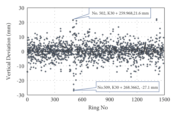
Figure 13 illustrates the distribution of the total deviation values; 90 percent of the deviation values of the rings are smaller than 13.0 mm, whereas 95 percent of the deviation values are smaller than 16.8 mm. The simulation results show a satisfactory assembly accuracy.

Furthermore, the mean value of deviation and the standard deviation can be calculated based on the possibility theory, the results of which are 6.0 mm and 1.7 mm, respectively.
6. Conclusion and Discussion
It is important to perform assembly simulation before determining UTSR geometric parameters during the design phase. This article describes the algorithms involved in the assembly of the UTSR system, including the position on the horizontal and vertical curves, the dichotomy to determine the ideal point on the DTA, and the computer graphics algorithm for rotating the space point around any axis. Based on these algorithms, a UTSR system assembly simulation program has been developed, which is capable of dealing with any tunnel with special rings inserted into its route. It is worthy of noting that in the process of shield tunneling, the actual tunnel axis deviation caused by unforeseen factors is inevitable. However, the UTSR system can manage to return the tunnel axis to the designed position as soon as possible by adjusting the relative angle between the preceding and following segmental rings.
This article takes a metro line tunnel located in Ningbo featuring a rather small radium and has been used as a case to validate the algorithm and illustrate the assessment methodology of universal tapered segmental ring assembly accuracy. The sections with maximum deviation are spotted as an alert ahead of the shield advancing. The assembly simulation methodology and software program have supported the construction of more than fifty tunnels, which illustrates its excellent suitability and robustness in shield tunnels throughout the construction.
In the future, further researches will be carried out in two aspects. One is to develop an intuitive and convenient tool to visualize the assembly simulation results for engineering applications. The other is to take five or more rings as a correction step and figure out the combination with minimum total deviation, so as to avoid rings with suddenly large deviations, for example, No. 502 ring and No. 509 ring of the background case.
Nomenclature
| TS: | Joint point of a tangent line and a spiral line |
| SC: | Joint point of a spiral line and a circular line |
| CS: | Joint point of a circular line and a spiral line |
| ST: | Joint point of a spiral line and a tangent line |
| PC: | Center point of a segmental ring |
| PT: | Trial calculation point |
| PI: | Intersection point on a horizontal curve |
| : | Length between the point located on a clothoid spiral and its origin point (TS or ST) (in m) |
| : | Length of a clothoid spiral (in m) |
| A1: | Azimuth angle of the line linking the previous PI and this PI (in degrees) |
| A2: | Azimuth angle of the line linking this PI and next PI (in degrees) |
| R: | Radius of a horizontal or a vertical curve (in m) |
| M: | Mileage pile value (in m) |
| x, y, z: | Coordinates (in m) |
| : | Gradient value (in %) |
| ξ: | Horizontal alignment deflection angle (in degrees) |
| Δ: | Intersection angle at PI (in degrees), “+” for right diversion and “−” for left diversion (in degrees) |
| θ: | Spiral angle (in degrees) |
| β: | Intersection angle of a circular curve (in degrees) |
| h: | Horizontal curve |
| : | Vertical curve |
| c: | Cross section |
| n: | Number of rings. |
Data Availability
The data used to support the findings of this study are available from the corresponding author upon request.
Conflicts of Interest
The authors declare that they have no conflicts of interest.